Many users in our community have asked: what’s the difference between Fusion 360 vs. Autodesk EAGLE? In this post, I’m going to share what made the move to Fusion 360 electronics the right path forward in our evolution from a point tool to a comprehensive product design solution.

For 30+ years, EAGLE was the solution for the user concerned with designing and manufacturing a PCB. EAGLE provided flexibility and an ability to personalize the software. It even had enough horsepower for those willing to dig deeper into its methodology(ies). Plus, the efficiency was hard to beat.
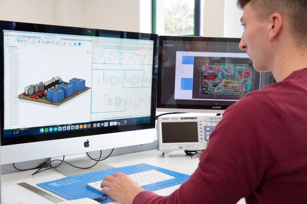
When EAGLE became a part of the Autodesk portfolio, we began a new chapter. Integrating electronics and mechanical design in a way never before possible. This was a great beginning, but it wasn’t anything like where we were headed. What we intended from the beginning was the ultimate integration of all the essential elements for true product design and manufacturing. As folks here quip, “if we intended to keep that a secret, we would have picked a better name than ‘Fusion.”
The intent was always to bring together the solutions Autodesk has for each stage of the design and manufacturing journey. The result enables you to get every part of your job done right and done well. The manufacturing capabilities in Fusion 360 enable you to create parts and assemblies, simulate toolpaths, and generate code for CNC machines. It also has the tools to design and 3D print models.
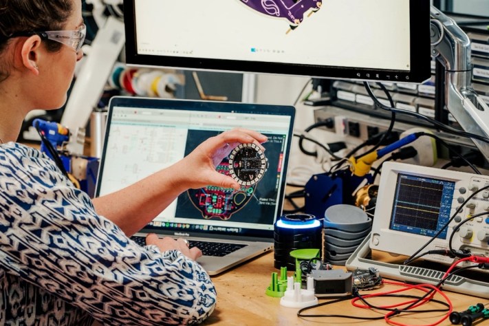
Fusion 360 electronics vs. Autodesk EAGLE — Why Fusion 360? Why Now?
Comparing EAGLE to Fusion 360 is an unfair comparison. One is a point solution, whereas the other is a true reflection of the end-to-end workflow we experience as engineers.
When you design a PCB, we know that you are concerned with programming, testing, and validating the PCB in multiple ways. Some of this happens in the design stage, but that is preparation for things to come. The myriad of jigs and fixtures being built just to hold a board, the clamshell tester which could be 3D printed, and the countless documents involved are foundational to a real product.
We are aware that bare boards and assembled PCBs are line items in a bill of materials and become part of the bills of process. Even further, price estimations go far beyond the PCB design workflow. Yet, we needed to deliver on the promise of serving our users and tackling their challenges. We couldn’t count on putting together scripts and files to provide a unified solution.
Our approach to answering your questions
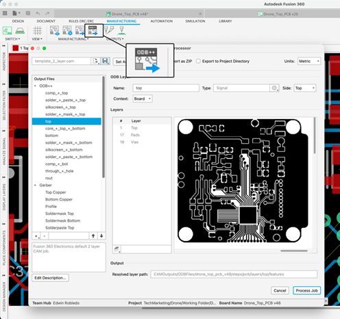
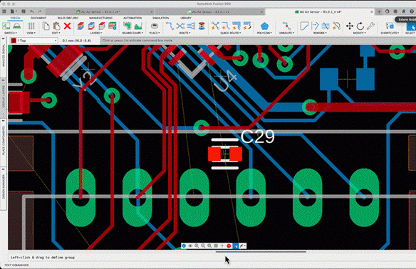
If you’ve followed our forums, you’ve seen the same requests coming up time and again — whether it be better manual routing, push and shove, differential pair support, length tuning, or improvements to output formats such as ODB++. Each time you’ve asked, our team has reached out more broadly to uncover the “why?” or, more importantly, “why now? what’s changed?”.
In the case of routing, that was obvious. PCBs have become more complex, and we needed to answer that with more powerful routing – done. Easy. In the case of ODB++, however, here is something that mirrors the goals of that end-to-end product design and manufacturing solution. ODB++ or IPC2581, billed as ‘comprehensive manufacturing files which contain 100% of the manufacturing information,’ highlight the need for every asset to be managed, every version of every asset to be up to date, and every output to be accurate.
Whether ODB++ or mechanical drawings, a 3D render, or animations, downstream colleagues and your business partners need the confidence that they have 100% of the data, wherever and whenever they need it. They must be confident that the information is current. That it’s annotated – replete with comments and history to document the state of the design and its progress. Your colleagues shouldn’t have to open the CAD system to access that information. They aren’t the CAD expert, you are.
Why Autodesk Fusion 360?
Fusion 360 is a cloud-based application that provides the benefits of collaboration and the accessible sharing of data. In addition, Fusion 360 natively includes design versioning, allowing you to return to any design stage if necessary.
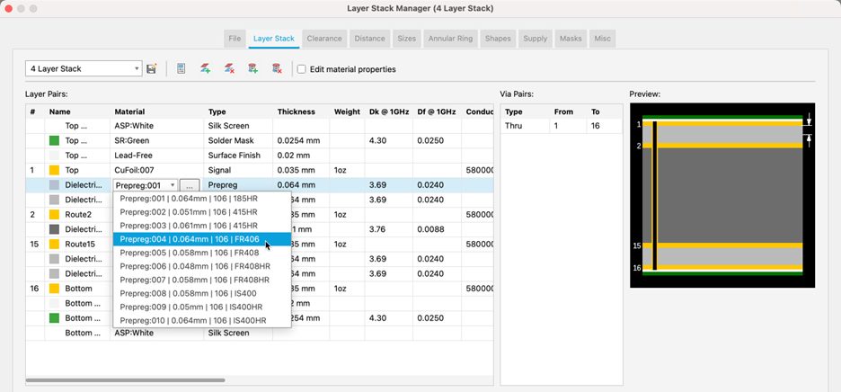
Prior to Autodesk, EAGLE’s interface to mechanical CAD was an IDF export ULP. Models were stored in files and folders, and the transformations from 2D to 3D required constant attention and were prone to errors. Moreover, mechanical drawings, dimensioning, associativity, and timeline-friendly updates to the mechanical designs were all infinitely more complicated due to the limited availability of 3D models of electronic components.
Listening to users, the team forged ahead first with synchronization between Fusion 360 and EAGLE, using a native mechanical format. We went on to build managed libraries and the Package Generator to bring together IPC-compliant footprint generation with the automated generation of 3D models, which contain physical materials, render-friendly UVs and textures, and are fully parametric.

Fusion 360 – wherever, whenever
Whether it is a mechanical drawing of a PCB, a 3D model of the finished product with the board(s) in their enclosure, a high fidelity photo-realistic rendering for a bid or presentation, or animations of the board assembly or the box-build of the final product; Fusion 360 provides countless assets that enable people along the extended product design and manufacturing workflow to get their jobs done.
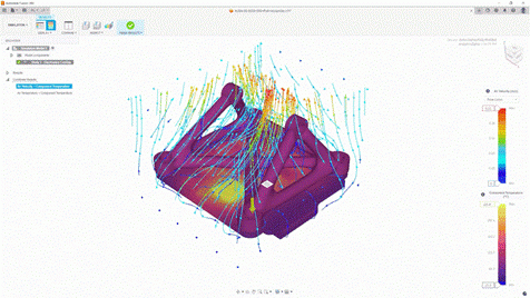
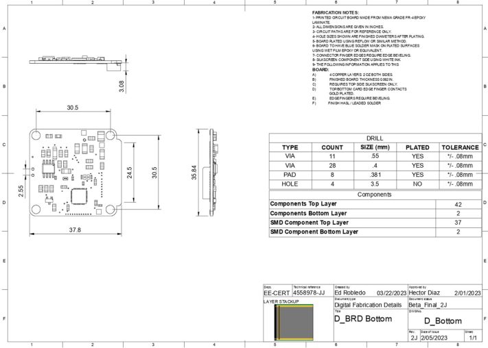
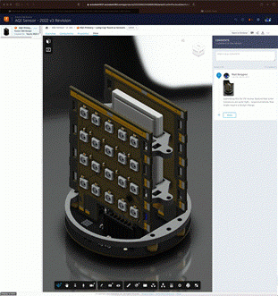
What EAGLE provided as output was an answer to one of those problems – the manufacture of the PCB. What Fusion 360 enables is something altogether more valuable. So, whether you’re working with a technician to assemble a prototype or someone on the factory floor to explain the assembly of the finished product, Fusion 360 gives stakeholders any time access to your data with Fusion Team, included with Fusion 360. This accelerates your documentation time and eliminates the need for CAD expertise. You can open or even export the information with viewers that show the rich details of your design.
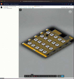
Fusion Team also ensures the latest version of your design information is always front and center. It shows you when two assets are out of sync and maintains a version history of each saved version. This helps you manage your time and maintain your design history. With online viewers that support comments and redlining, a list of parts along with the 3D viewable makes hand assembly easy, using only a web browser.
The addition of Fusion Team eliminates the need for so many scripts and print outputs, PDFs, etc., without eliminating your ability to produce them. Fusion users use annotations to point out specific test points or compile notes to those on the factory floor. Users can share but also control access to any document. They can set permissions to view or edit documents with teams and folder permissions. Users can manage access across the organization and beyond.
How to migrate from EAGLE to Fusion 360 electronics
In just a few years, Autodesk accomplished what many felt was impossible. Not only did we achieve it, but we exceeded expectations — bringing EAGLE into the future of design manufacturing.
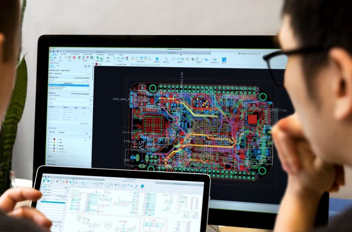
Many of you might ask how easy or long it will take you to get used to a new interface. Here’s a migration guide from my long-time colleague, Richard Hammerl. Learn how to easily get up to speed with Fusion 360 electronics and integrate your EAGLE design and library files.
I recently held a workshop at a local university in Miami. The classroom was packed with engineering students from different majors: Electronics, Robotics, Mechanical, Biomedical, and more. The typical comment was that they prefer working in Fusion 360 because it unifies all their disciplines in one platform. Electronic and mechanical engineers collaborate and adapt to changes quickly. They all stated that Fusion 360 was much easier to use than other applications they had access to.
Join the thousands that have decided to migrate to Fusion 360 electronics and get your products to market sooner.

